
Audit ready schematics for UK water systems, HSE aligned

A schematic drawing is a simplified, accurate illustration of a water system’s layout, showing tanks, pipework, valves and outlets without the technical clutter of an as-built water system diagram engineering plan. It exists to make legionella risk visible: temperatures, dead legs, aerosol sources and monitoring points, all in one page that a non-specialist can read. HSE’s Approved Code of Practice L8 treats an up-to-date schematic as a required part of the risk assessment and written scheme. Success looks like one clearly annotated diagram, dated and referenced directly in your risk records.
TL;DR:
A schematic shows only system logic, not full engineering detail, making it easier for non-specialists to trace water flow and identify legionella risks.
Regulatory standards require an up-to-date schematic to be part of the risk assessment, with key features like dead legs, sentinel outlets, and temperature targets clearly marked.
Creating a compliant schematic involves site surveys, consistent symbols, validation against actual systems, and proper documentation such as version control and sign-off procedures.
Regular review of the schematic is necessary after any system changes, remedial work, or positive legionella tests to keep records accurate and compliant.
Integrating schematic surveys into routine site visits and using software like CAD or Revit improves accuracy, facilitates audits, and supports ongoing risk management.
Table of Contents
What schematic drawings are and why they matter for water systems
A schematic is not an as-built drawing. As-built plans show every pipe run, joint and dimension for construction and maintenance purposes. A schematic strips that back to what a risk assessor actually needs: system logic, not engineering precision. HSG274 Part 2 describes it as a simplified, accurate illustration meant to be readable without specialist training, and that distinction matters more than it sounds.
Facilities teams change staff, contractors rotate, and auditors arrive with no prior knowledge of your buildings. A well-drawn schematic lets any of them trace water from source to outlet and spot where legionella bacteria could establish itself, whether that is a cold tank sitting too warm, a length of pipe that rarely flows, or a shower head throwing aerosols into a poorly ventilated room.
Why regulators care so much about this one document:
HSE L8 lists an up-to-date schematic as an expected element of the legionella risk assessment and written scheme.
HSG274 requires the diagram to show plant, control valves, outlets, strainers, filters and any parts temporarily out of use.
HSE’s guidance on what you must do links schematic availability directly to your review and recording obligations.
What a good schematic must show
A schematic earns its place in an audit file only if it actually shows the things an inspector or risk assessor will ask about. Get the plant and the annotations right, and the drawing does most of the explaining for you.
Start with the physical components every schematic needs:
Cold water storage tanks and any break tanks
Calorifiers, water heaters and plate heat exchangers
Circulation and booster pumps
Isolation, servicing and control valves
Strainers and filters
Thermostatic mixing valves (TMVs)
All outlets, including showers, taps and hose points
Beyond the hardware, HSG274 flags specific risk conditions that need marking on the drawing: dead legs, little-used outlets, bypasses, sample taps and sentinel outlets (the outlets furthest and nearest from the water source on each circuit, used to check temperature performance). Flow arrows, a legend explaining every symbol, and a clear version date with author contact details turn a sketch into a usable compliance record.
Pro Tip: Colour-code hot and cold pipework and mark every sentinel outlet with its target temperature range directly on the drawing. It saves a monitoring technician from cross-referencing a separate spreadsheet every visit.
How to create a clear water system schematic
Producing a schematic that survives an audit takes a defined sequence, not a single afternoon with a clipboard.
Survey the site. Walk every riser, plant room and outlet, recording each component into an asset register as you go. This becomes the raw data for the drawing and the backbone of your ongoing compliance records.
Choose your drafting method. A hand sketch works for a first pass, but most sites move it into Visio, AutoCAD or Revit for a cleaner, exportable version. Export the final file as a PDF so it drops straight into a physical or digital logbook without needing specialist software to open.
Apply consistent symbols. Use one symbol set throughout so a plumber, an assessor and a fire officer can all read the same page without a briefing.
Validate on site. Walk the finished drawing against the actual system before sign-off. Label every sample point physically on-site to match the drawing’s references.
Hand over to operations. File the signed schematic where the responsible person and any contractor can find it immediately, not buried in a project archive.
Using schematics in the risk assessment and written scheme
A schematic only earns its keep when the risk assessment actually uses it. Every marked feature should map to a real risk factor: a dead leg becomes a stagnation risk, a shower outlet becomes an aerosol source, a calorifier becomes a temperature-control point that needs checking against the 50°C to 60°C range typically required at outlets.
HSE’s L8 code expects the written scheme to include an up-to-date plan of the water system alongside monitoring procedures and remedial records, so the schematic and the paperwork need to describe the same system, version for version. What belongs in the written scheme:
The schematic’s location, version number and date of last review
Zones identified as higher risk, with the reasoning behind that flag
Monitoring points cross-referenced to their position on the drawing
Certain events should trigger an immediate schematic review rather than waiting for the next scheduled check:
Any alteration to pipework, plant or outlets
Remedial works, including disinfection or tank replacement
A positive legionella sample result or a suspected case linked to the site
Reviewing an existing legionella risk assessment is the natural moment to check the schematic still matches reality.
A practical method-of-works for schematic creation
Bespokecompliancesolutions applies a documented method-of-works that treats the schematic as one deliverable in a longer chain, not a standalone drawing exercise. The sequence runs survey, then schematic, then annotated deliverable, then logbook entry, so nothing produced on-site gets lost before it reaches the compliance file.
Checklist items built into that process include:
Every sample tap labelled to match its physical location and its position on the drawing
TMV references cross-checked against the asset register
Automated temperature monitoring points tied directly to the sentinel outlets marked on the schematic
Consistent handover paperwork like this cuts audit preparation time significantly, because the assessor is checking one coherent record rather than reconciling three different versions of the same building.
Reading a sample schematic: riser loops and dead legs
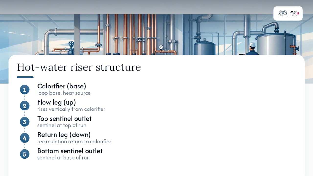
A hot-water riser excerpt typically shows the flow and return legs of a recirculation loop, with the calorifier at the base and sentinel outlets marked at the top and bottom of the run. Riser diagrams built in CAD or Revit make the vertical relationship between these loops far easier to follow than a flat floor plan, which matters when you are checking that return water still meets temperature targets after a long climb.
On a small-office schematic, dead legs usually show up as short pipe stubs feeding rarely used cupboards or decommissioned outlets. Mark these with a distinct symbol and a note explaining why the section still exists.
For handover, keep file names consistent (site, building, revision date) and store one master PDF that contractors and auditors both reference, never separate marked-up copies.
What facilities teams get wrong with schematics
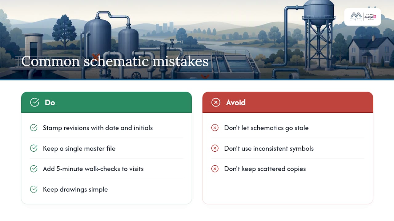
The most common failure is not a badly drawn schematic. It is a correct one left to go stale: a tank gets replaced, a shower gets removed, and nobody touches the drawing. Inconsistent symbols between buildings on the same site cause almost as much confusion.
Fix it cheaply. Stamp every revision with a date and initials, keep one master file rather than scattered local copies, and build a five-minute walk-check into routine monitoring visits. Keep the drawing simple enough for a new starter to read, then attach a technical appendix for engineers who need the detail.
— Sammi
Keep your schematics survey ready, always
Some companies integrate schematic surveys directly into site work rather than treating them as a separate paperwork exercise, which results in one annotated drawing matching the asset register instead of two documents drifting apart over time.
[

A Legionella Risk Assessment from £185 includes the schematic survey, asset register linkage and a handover pack you can drop straight into your logbook. If your monitoring points need tying to sentinel outlets marked on the drawing, automated water temperature monitoring can be set up against the same schematic, and tank work identified during the survey can be scheduled through water tank cleaning and disinfection. Organizations can arrange a site survey and request a quotation for their buildings.
FAQ
What Is a Water System Schematic Drawing?
It is a simplified, accurate diagram showing a water system’s tanks, pipework, valves and outlets, drawn so a non-specialist can follow it. HSG274 treats it as distinct from an as-built engineering drawing because it prioritises clarity over technical precision.
What Does a Typical Schematic Diagram Example Include?
A typical example shows cold water storage tanks, a calorifier, pumps, valves, TMVs and outlets, with flow arrows and a legend explaining every symbol. Risk features like dead legs and sentinel outlets are marked separately so they stand out from the general layout.
How Do You Create a Simple Schematic Diagram?
Survey the site and log every component into an asset register, sketch the layout by hand or in software such as Visio or CAD, then validate the finished drawing against the real system before sign-off. Export the approved version as a PDF for the compliance logbook.
Does a Water System Have a Phase Diagram Like Other Physical Systems?
A water system’s compliance schematic is not the same as a scientific phase diagram, which maps states of matter under pressure and temperature. For legionella management, the relevant diagram is the system schematic showing layout, flow and risk points, not a thermodynamic phase chart.
How Often Should a Schematic Be Reviewed?
Review it whenever the system changes, after remedial works, or following a positive legionella sample, rather than waiting for a fixed annual date. HSE’s guidance links this directly to your ongoing risk assessment review process.
Recommended
Comments